How Application Temperature Affects Thermal Label Adhesion
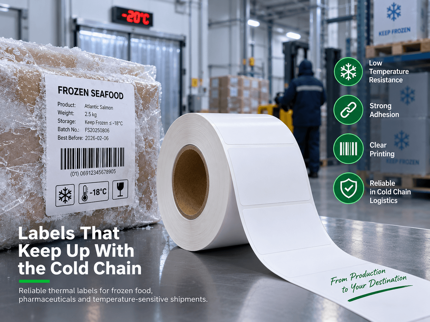
A thermal label rated for service at −40°C can still peel when first applied to a cold carton. The adhesive may tolerate freezing after a bond has developed but need a warmer surface to form that bond. For buyers investigating cold-weather failures, the starting point is to separate application temperature from service temperature, then test the actual packaging and process.
Read the two temperature specifications separately
Minimum application temperature is the lowest recommended temperature for applying the label under the supplier’s stated conditions. Service temperature is the range the applied label is intended to tolerate after correct application and any required bond-development period.
As a product-specific example, Zebra’s US Z-Essentials 500D specification lists a minimum application temperature of 4°C and a service range of −40°C to 60°C. Those figures illustrate the distinction; they are not specifications for other thermal labels or for HY-paper materials. Confirm the current datasheet for the exact construction being purchased.
Do not select a material from its lowest service-temperature number alone. Ask about application conditions, any waiting period before cold storage, and the complete construction. Adhesion and printed-image readability are separate performance checks.
Understand what changes at low temperature
Pressure-sensitive adhesive needs close contact with the substrate to form a useful bond. This is often called wet-out. Many adhesives become firmer and less tacky as temperature falls, making that contact harder to establish.
Rough corrugated board can limit contact, but a smooth surface is not automatically easy to label. Plastic type, surface energy, coatings and contamination also matter. Polyethylene and polypropylene, for example, can require adhesive selection that accounts for their low surface energy.
Measure the packaging and check for moisture
A warehouse air reading does not establish carton temperature. Packaging unloaded from a refrigerated vehicle or taken from a cold room may remain colder than the surrounding air. Measure the substrate at the point of labelling and record the label roll’s temperature and storage history too.
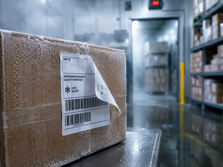
Condensation may form when a cold surface enters warmer humid air. Water or frost can interfere with adhesive contact. Test cold dry packaging separately from cold damp packaging; a low-temperature adhesive is not automatically suitable for wet or frosted surfaces. Discuss drying, a different application point, or a construction intended for the actual moisture conditions.
Include colder-month conditions in approval testing, even if initial trials take place in warmer months. Record temperature and humidity rather than using the season as a proxy. This also makes results easier to compare across sites and countries.
Separate application pressure from bond-development time
A hand-applied sample may receive more pressure and more even contact than a label on a fast automatic line. If manual application succeeds but production fails, inspect applicator pressure, roller condition, speed, alignment and contact across the label.
Application contact time is the time spent pressing the label onto the surface. Dwell time here means the elapsed time after application before testing or exposure to the next process step. They are different variables. Ask the material supplier whether the construction needs a specified interval before entering cold storage, and reproduce the real interval during testing.
General pressure-sensitive adhesive guidance explains how pressure, time and temperature affect contact. It does not establish a universal waiting period for every label adhesive.
Run a controlled comparison before changing material
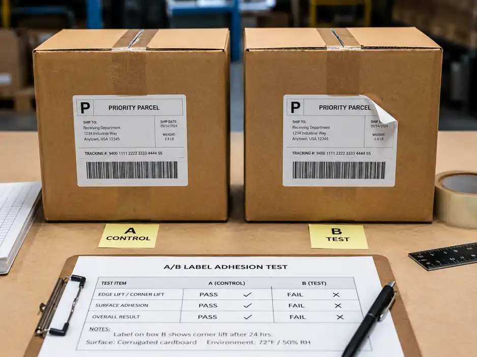
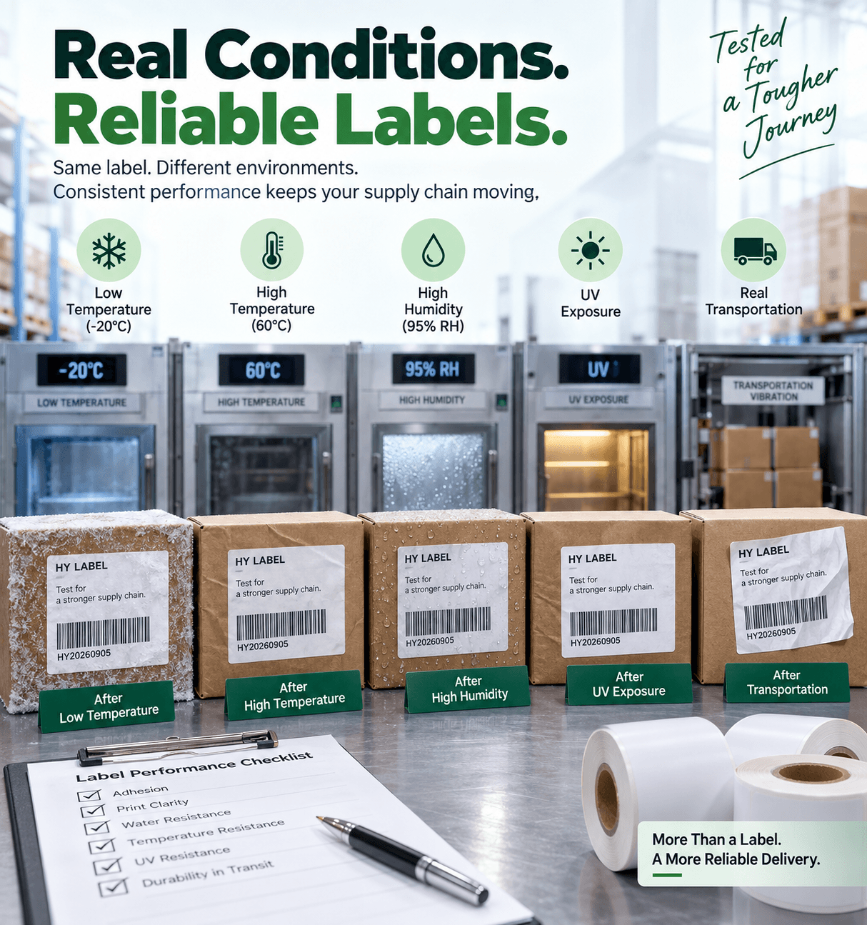
Compare the current material with a proposed alternative on packaging from the same batch. Apply both at a normal reference temperature and at the actual low application temperature. If condensation occurs in production, add a separate condition that reproduces it. Use multiple samples per condition rather than judging a single label.
Keep label size, application method, pressure and handling consistent. Record material and packaging batch references, substrate and roll temperatures, surface moisture, time before cold storage, and inspection times. Check immediate hold, edge lift, movement and performance after realistic storage and handling. Also scan the printed label after exposure.
Define success before testing. For a permanent shipping label, reliable attachment through the required journey is the priority. Fibre tear during removal can be recorded, but it is not a universal pass criterion. For a removable label, evaluate attachment during use and clean removal after the required dwell and temperature exposure. Record residue and surface damage separately.
Use failure patterns to narrow the investigation
- Works after the carton warms up: investigate application temperature while also checking whether surface moisture changed.
- Fails mainly on damp packaging: investigate moisture tolerance and the application point.
- Sticks initially but fails in cold storage: check the service range, bond-development interval and complete label construction.
- Works on one carton batch only: check substrate coatings, texture and contamination as well as temperature.
Put measurable requirements on the order
Use a defined application profile instead of “freezer label” or “strong glue”. The following is an illustrative requirement, not a claim that a particular material will pass:
- Application surface temperature: as low as 0°C.
- Expected service range: −20°C to +40°C.
- Substrate: recycled corrugated carton.
- Method: automatic print-and-apply; possible condensation.
- Bond requirement: permanent.
- Minimum time before cold storage and required label life:supplied by the buyer.
Also provide label dimensions, DT or TT print method, printer model, line speed and a packaging sample where possible. Agree the selected material reference, storage instructions and sample acceptance criteria before production. If the actual process falls outside the stated conditions, retest rather than relying on the original approval.
Frequently Asked Questions
Does permanent adhesive mean freezer-compatible?
No. It describes the intended bond type. Both application and service conditions must match the selected construction.
Do all cold-chain labels need freezer-grade adhesive?
No. A label applied in warmer conditions may be suitable for later cold storage if its service rating and required bond-development conditions cover the process. Low-temperature application requires separate confirmation.
Should I choose the lowest temperature rating available?
Choose a construction supported by your actual requirements and sample results. A more extreme rating does not by itself resolve moisture, substrate or applicator problems.
Discuss your application conditions
If labels are lifting, send HY-paper the substrate type, measured application temperature, storage conditions and photos of the failure. Include whether the surface is damp and how soon the package enters cold storage. This gives us a clearer basis for discussing material options and a relevant sample trial.